Instructions for steering wheel setup: hardware
Version 1.2.0, 23 June 2020
Lauren E Wool*, Miles J Wells**, Hamish Forrest, and Matteo Carandini
Cortical Processing Laboratory, University College London
Assembling the water-reward system
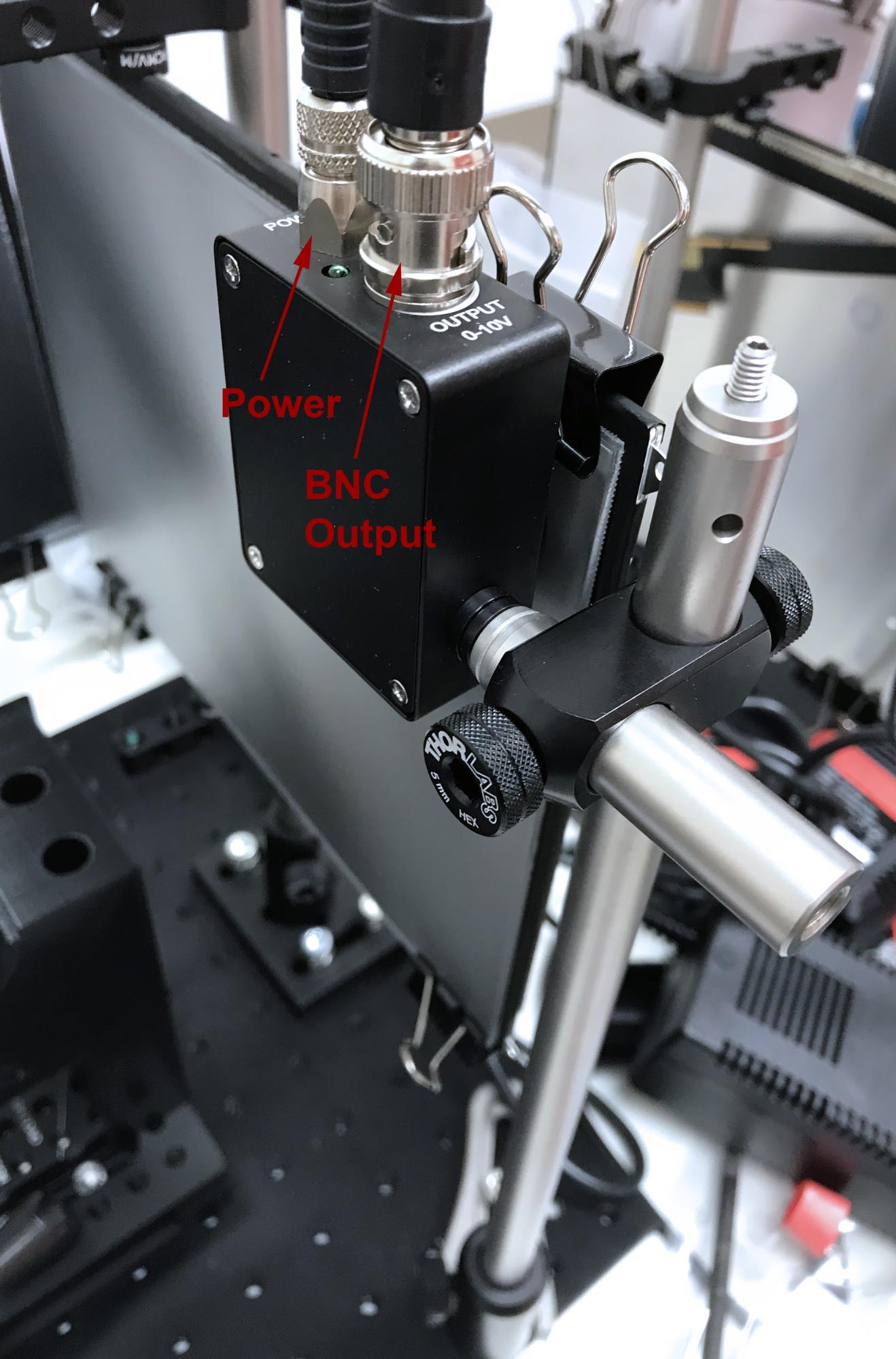
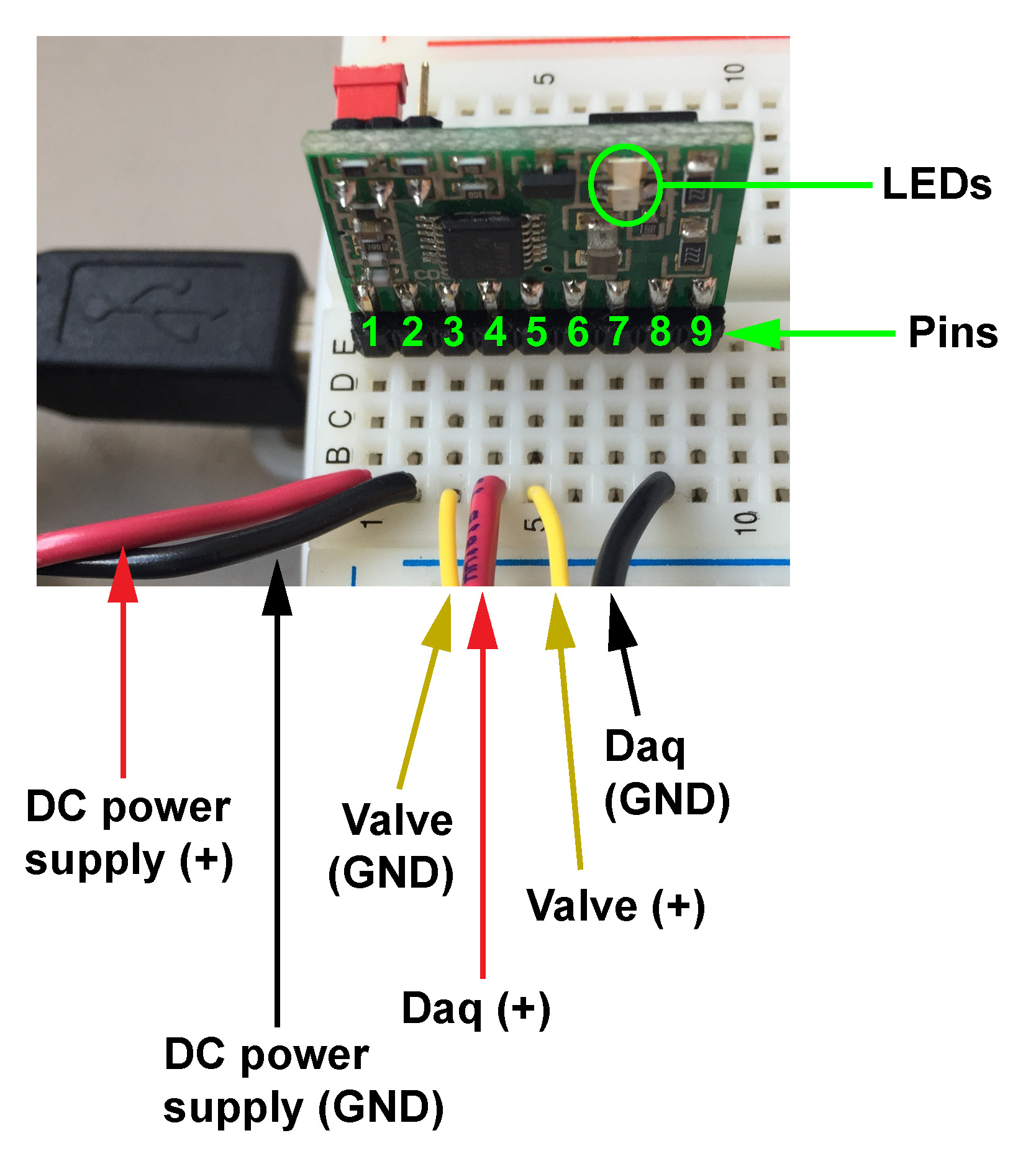
Connecting the water-reward system
This document gives instructions on how to build a basic version of the steering wheel setup to probe mouse behavior, introduced by Burgess et al. (Cell Reports, 2017). The goal is to make it easy for other laboratories, including those that make the International Brain Laboratory, to replicate the task and extend it in various directions. To this end, these instructions rely entirely on materials that can be bought off the shelf, or ordered online based on 3-D drawings.
In this steering wheel setup, we place a steering wheel under the front paws of a head-fixed mouse, and we couple the wheel’s rotation to the horizontal position of a visual stimulus on the screens. Turning the wheel left or right moves the stimulus left or right. The mouse is then trained to decide whether a stimulus appears on its left or its right. Using the wheel, the mouse indicates its choice by moving the stimulus to the center. A correct decision is rewarded with a drop of water and short intertrial interval, while an incorrect decision is penalized with a longer timeout and auditory noise.
We use this setup throughout our laboratory, and deploy it in training rigs and experimental rigs. Training rigs are used to train head-fixed mice on the steering-wheel task and acquire behavioral data. Experimental rigs have additional apparatus to collect electrophysiological and imaging data, measure eye movements and licking activity, provide optogenetic perturbations, and so on.
Up until recently, constructing these setups required a machine shop that could provide custom-made components. However, for the purposes of spreading this setup to other laboratories, we here describe a new version that does not require a machine shop: all components can be ordered online or 3D-printed.
NB: An improved frame design can be found on the IBL Website. The improved frame and its components (mouse holder, etc.) may still be used with Rigbox.
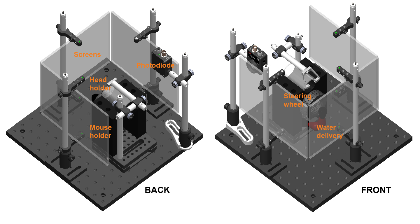
The behavioral rig. A basic behavioral setup with three iPad screens (with Fresnel lenses), a mouse holder (with steering wheel), a water-delivery system, a head-fixation assembly, and a photodiode.
The main components of the behavioral setup are a mouse holder with steering wheel encoder, a water-delivery system, and three iPad screens for stimulus presentation. These and other components are held together by a “frame”. A “stimulus computer” controls all this apparatus. Additionally, a “master computer” controls the stimulus computer.
A 3D view of the rig is available here, and a detailed list of the components can be found in the spreadsheet at the bottom of the page. Note that this list was assembled in the UK; though we have aimed to use international vendors, you may need to pick different ones depending on your location (please let us know if you encounter difficulties). Place the orders as soon as possible, as some items will take time to arrive. Also, start planning how you will 3D-print the mouse holder.
Configuring the “stimulus computer” is more involved, and so it helps to have it in place first. This way you can use it to test other components as they arrive. The “master computer” can be configured once you are ready to run software.
The “master computer” controls the stimulus computer and manages the experimental session, and monitors the mouse with a camera. It runs Windows 10. The computer should be connected to the network, ideally through a high-speed connection (not WiFi). Instructions for installing and managing experimental software for this computer can be found in the document "Software instructions for steering wheel setup." If you are not using our software, you do not necessarily need this computer.
The “stimulus computer” controls stimulus display and water delivery, and acquires the mouse’s movements on the steering wheel and the output of a photodiode to synchronize stimulus output with other measurements. It runs Windows 10. The computer should be connected to the network, ideally through a high-speed connection (not WiFi). Instructions for installing and managing experimental software for this computer can be found in the document "Software instructions for steering wheel setup."
The required video card is the NVIDIA NVS 510. This card drives four monitors: a main display monitor and the three iPad screens. This is a typical installation that would apply to any card for a Windows machine; if you are not familiar with the process, detailed instructions are below.
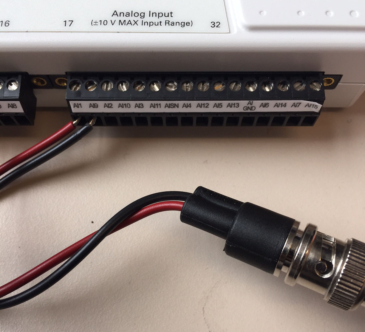
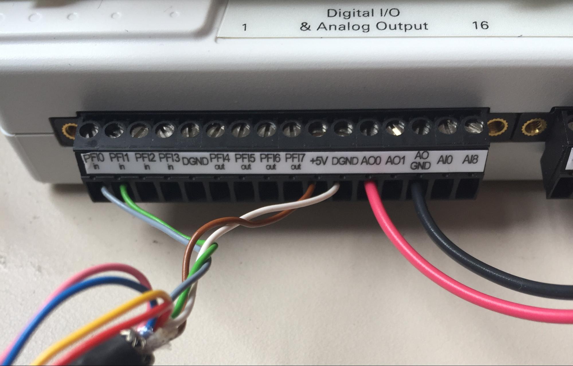
To acquire data from the steering wheel and from the photodiode and to deliver water rewards to the mouse, we use a DAQ (data acquisition) device, the NI-DAQ 6211.
The setup itself comprises three iPad screens installed on posts, a mouse holder with a steering wheel encoder and head-fixation assembly, and a water-delivery system. Here we describe the assembly of the frame required to hold these and other components together.
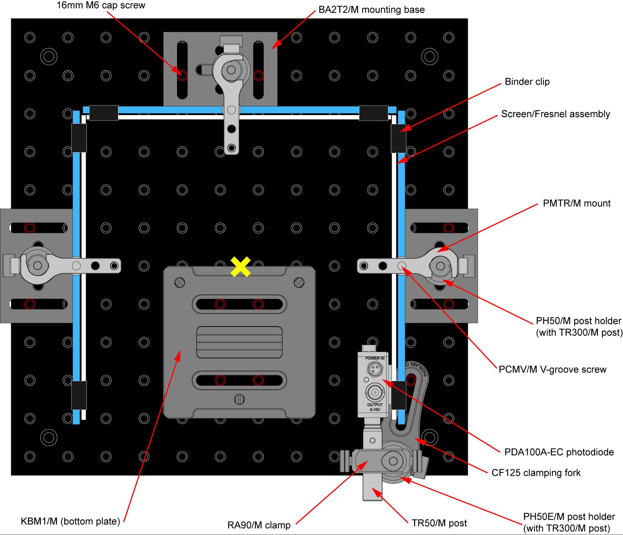
Rig footprint diagram. The steering-wheel setup is contained entirely within a frame made of Thorlabs components, all seated on a 300mm x 300mm aluminium breadboard (MB3030/M). Components can be secured to the breadboard using 16mm M6 cap screws. The screen/Fresnel assemblies are seated between two grooved screws on clamps (one bottom, one top) that are attached to 300mm posts. The mouse itself is seated on a 3D-printed holder (not shown) that attaches to a magnetic plate in the center of the frame. In order for the Fresnel lenses to collimate light properly, the mouse’s head position must be equidistant from the three screens (indicated by the yellow ‘x’). This requirement is fulfilled with proper attachment of the holder to the magnetic plate (described below).
The frame is composed chiefly of Thorlabs components.
To protect the screens from damage, keep the plastic film on until you are ready to attach the Fresnel lenses
The purpose of the Fresnel lenses is to ensure that the intensity is homogeneous across the screen when viewed from a specific location (marked by a yellow ‘x’ in the rig footprint diagram above). To avoid pixel aliasing, the iPad screen and Fresnel lens must be separated by ~1 mm, using silicone pads. Various brands of window film may have different application instructions, so you may need to adapt steps 2–13 below.
If you haven't already done so, ensure that the main monitor of the Stimulus computer is connected to the NVIDIA video card via a mini-DisplayPort cable, at port 4.
The three iPad screens must be designated as a single viewable output, separate from the main monitor. This is accomplished using the NVIDIA Control Panel.
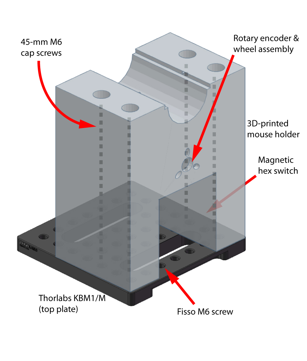
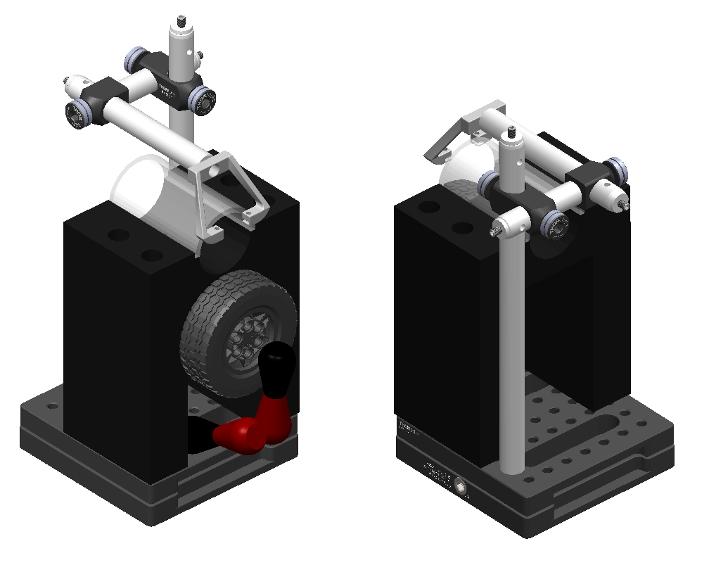
The mouse holder comprises seating for the mouse, a steering wheel/encoder assembly, an articulated arm for delivering water rewards, and a head-fixation assembly.
The mouse holder assembly. Left: The mouse holder, seen from the front, shows the center bore that will accommodate the wheel assembly, as well as key attachment points to the KBM1/M breadboard. Center: The front of the holder shows the attachment point for the Fisso arm. Right: The back of holder shows the attachment point for the head-fixation assembly.
A camera is essential for monitoring the mouse’s behavior during the task, and a speaker is necessary to transmit simple task-related sounds, like beeps and white noise.
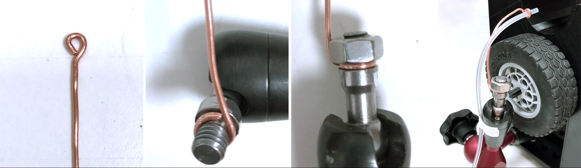
Making a spout guide. Use a length of 16AWG copper wire to extend the reach of the Fisso arm and enable water delivery to the mouse.
Before troubleshooting, always power off the valve system by unplugging the power supply directly.
A photodiode is critical for gamma-correcting the luminance output of the screens, and is important for measuring stimulus timing. However, it is not required for starting basic behavioral training and can be added at a later stage.
Now that you have your behavioral setup, you will want to place it in a sound insulation box or other quiet place to train your mice, or somewhere else in your lab, where you can acquire physiological data.
In following these instructions, you certainly will find that parts of this document can be improved. By all means, please make those improvement, by using the “suggest” feature if you are reading this in Google Docs, or by sending an email to Lauren or Miles.
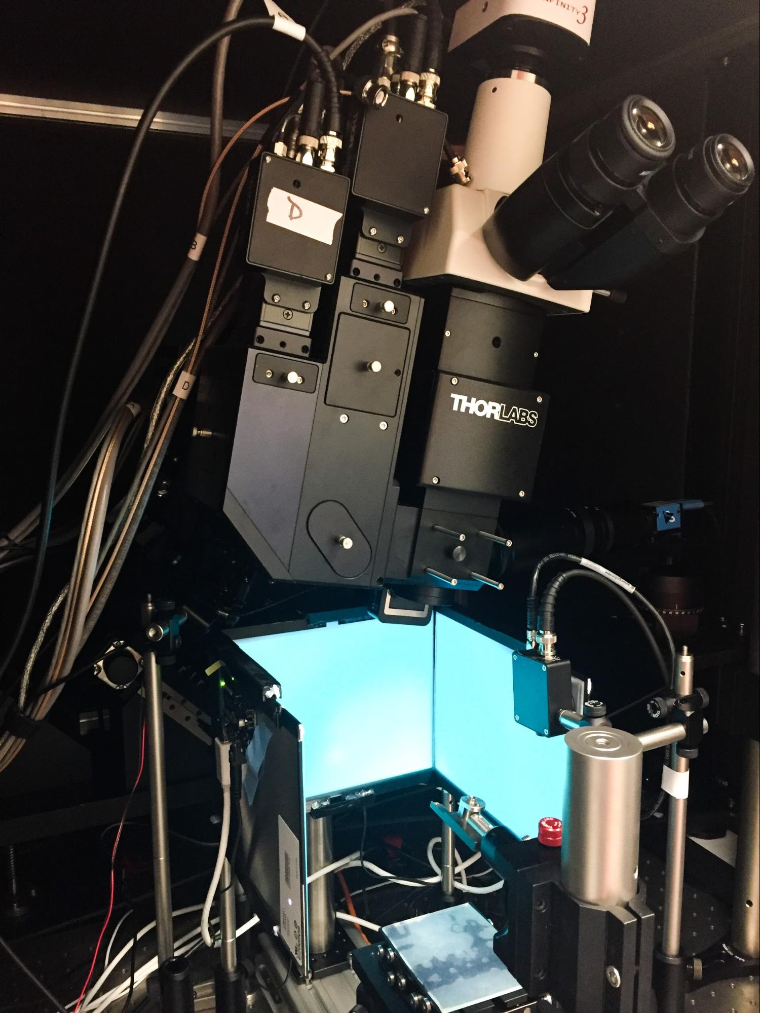
An example of a steering-wheel setup used in a 2-photon imaging rig
|
Category |
QTY |
Product |
Specifications |
Supplier |
Notes |
|
Stimulus computer |
1 |
Computer |
Processor: Intel Core i3 7100, 3.9 GHz Memory: 16 GB (2 x 8 GB) Corsair 2133MHz DDR4 RAM, 1.2 V Storage: 1TB WD Blue WD10EZEX, 7200rpm, 64MB Cache OS: Windows 10 64-bit |
Scan V10i |
This computer controls the rig. For more details, see the document: "Software Instructions for Steering Wheel Setup". Note: When building multiple rigs, EACH rig needs its own Stimulus Computer, but these can all be controlled by one Master Computer |
|
1 |
Graphics card |
NVIDIA NVS 510 |
Insight Cat# VCNVS510VGA-PB |
|
|
|
1 |
Keyboard & mouse |
|
|
|
|
|
1 |
Monitor |
|
|
|
|
|
1 |
mini-DP display cable |
|
|
Connects the monitor to the video card |
|
|
1 |
USB stereo speaker |
|
Adafruit 3369 |
|
|
|
Master computer |
1 |
Computer |
Processor: Intel Core i3 4170, 3.70 GHz Memory: 4 GB (2 x 2 GB) DDR3/DDR3L OS: Windows 10 64-bit Graphics Card: On-board graphics support |
HP ProDesk 400 G2.5 (or similar) |
This computer controls the Stimulus Computer. For more details, see the document: "Software Instructions for Steering Wheel Setup". Note: When building multiple rigs, EACH rig needs its own Stimulus Computer, but can all be controlled by one Master Computer. If you are not using our software, you do not necessarily need this machine. |
|
1 |
Keyboard & mouse |
|
|
|
|
|
1 |
Monitor |
|
|
|
|
|
1 |
USB camera |
|
Logitech C270 |
|
|
|
Stimulus displays |
3 |
iPad 3/4 Retina display |
LP097QX1 |
Adafruit 1751 |
|
|
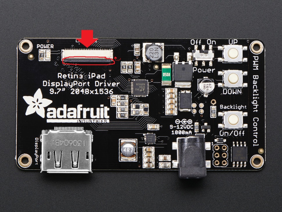
3 |
Qualia bare driver board |
|
Adafruit 1716 |
|
|
|
3 |
Mini DP-to DP cable |
DisplayPort 1.2, 2m length |
StarTech MDP2DPMM2M |
|
|
|
3 |
9V DC, 1A power supply |
9V DC, 1A, 1 output |
RS 720-3726 (UK) / 720-3720 (USA/Japan) / 720-3739 (EU) |
|
|
|
3 |
Fresnel lens |
Size: 200 x 160 mm Thickness: 2mm Material: PMMA Groove pitch: 0.5mm Focal length: 220mm |
Edmund Optics (request the listed specifications) |
Cortexlab have a number of these lenses cut to spec; please contact us if you are interested in obtaining some for your build |
|
|
1 |
Roll adhesive window film (50 cm x 5 m) |
Smooth surface, frosted-effect, adhesive (not self-adhesive/static) |
The Window Film Company "Frostbrite" (or similar) |
|
|
|
12 |
Binder clips |
19mm |
Staples 831594 |
|
|
|
1 |
Roll silicone rubber sheet |
600mm x 600mm x 1.5mm |
RS 840-5541 |
|
|
|
Mouse holder |
1 |
Incremental rotary encoder |
24mm, push-pull, 5V, 1024 PPR |
Kubler 05.2400.1122.1024 |
|
|
1 |
USB data acquisition (DAQ) I/O device |
Interface for rotary encoder and water reward system |
National Instruments USB-6211 |
|
|
|
1 |
LEGO wheel/axle hub |
Wheel 62.4 x 20 with Short Axle Hub, with Black Tire 62.4 x 20 (86652 / 32019) |
LEGO parts 86652 & 32019 (www.bricklink.com) |
|
|
|
1 |
Mouse holder block |
|
|
||
|
1 |
Mouse holder block cover |
|
|
||
|
1 |
Wheel/encoder coupler |
|
|
||
|
3 |
5mm M3 screw |
|
Thorlabs SH3M5 (or part of HW-KIT5/M) |
SH3M5 is a pack of 50, but only 3 total are required |
|
|
4 |
45mm M6 cap screw |
|
RS 293-397 (or part of Thorlabs HW-KIT2/M) |
RS 293-397 is a pack of 50, but only 4 total are required |
|
|
1 |
Post |
|
Thorlabs TR200/M |
|
|
|
1 |
Post |
|
Thorlabs TR50/M |
|
|
|
1 |
Post |
|
Thorlabs TR100/M |
|
|
|
1 |
Right-angle clamp |
|
Thorlabs RA90/M |
|
|
|
1 |
Right-angle end clamp |
|
Thorlabs RA180/M |
|
|
|
1 |
20mm M6 set screw |
|
Thorlabs SS6MS20 (or part of HW-KIT2/M) |
SS6MS20 is a pack of 25, but only 1 is required |
|
|
1 |
Magnetic breadboard |
|
Thorlabs KBM1/M |
|
|
|
1 |
Aluminium Headplate Holder |
Thread size for the 2 thumbscrews: M3 Material: Aluminium 6082 - T651 Grey Aluminium |
On ProtoLabs.com, click 'Get a quote', select 'CNC Machining' and upload the STL file. |
||
|
2 |
Stainless thread M3 thumb screw |
6mm shaft |
Mechanical Components P0480.030-006-A4 |
|
|
|
1 |
Stainless steel headplate |
|
|
||
|
1 |
Articulated arm |
Strato XS-13 130 mm with M6 mounts (arm only) |
Fisso 4.000 |
||
|
1 |
Roll copper wire |
Solid core, bare, 16 AWG |
RS 357-794 |
|
|
|
1 |
M6 hex nut |
|
RS 525-919 (or part of Thorlabs HW-KIT2/M) |
RS 525-919 is a pack of 250, but only 1 is required |
|
|
Reward system |
1 |
Pinch valve |
1-tube, normally closed, 12V DC |
NResearch 225P011-21 |
|
|
1 |
Valve controller driver |
Nresearch CoolDriveSolo CDS-V01 (UK), CoolDriveSolo CDS-US (USA) |
Confirm the linked specifications, as part numbers can be inconsistent |
||
|
1 |
Tubing |
1/32" ID x 3/32" OD, 50 ft |
Cole Parmer WZ-95702-00 |
|
|
|
2 |
Tube connector |
Barbed Reducing Connector 3/32" x 1/16" |
Cole Parmer WZ-41518-22 |
|
|
|
1 |
Power supply |
1.5–12 V DC, 1A linear power supply |
RS 615-8919 |
|
|
|
1 |
Mini breadboard |
|
Pimoroni COM0101 |
|
|
|
1 |
Cable mount |
2.1 x 5.5 mm DC (female), 2-pin |
RS 810-4605 |
|
|
|
1 |
Roll red hookup wire |
300V 22AWG, solid core |
Alpha Wire 3051/1 RD005 |
|
|
|
1 |
Roll black hookup wire |
300V 22AWG, solid core |
Alpha Wire 3051/1 BK005 |
|
|
|
Rig frame |
1 |
Breadboard |
|
Thorlabs MB3030/M |
|
|
3 |
Post |
|
Thorlabs TR300/M |
|
|
|
3 |
Post holder |
|
Thorlabs PH50/M |
|
|
|
3 |
Adjustable mounting base |
|
Thorlabs BA2T2/M |
|
|
|
6 |
Component clamp |
|
Thorlabs PMTR/M |
|
|
|
6 |
V-groove base adapter |
|
Thorlabs PCMV/M |
|
|
|
1 |
USB camera |
|
Logitech C270 |
|
|
|
1 |
USB stereo speaker |
|
Adafruit 3369 |
|
|
|
12 |
16mm M6 cap screw |
|
RS 281-114 (or part of HW-KIT2/M) |
RS 281-114 is a pack of 50, but only 12 screws total are required |
|
|
Photo- diode |
1 |
Post |
|
Thorlabs TR300/M |
|
|
1 |
Post |
|
Thorlabs TR50/M |
|
|
|
1 |
Right-angle clamp |
|
Thorlabs RA90/M |
|
|
|
1 |
Post holder |
|
Thorlabs PH50E/M |
|
|
|
1 |
Clamping fork |
|
Thorlabs CF125 |
|
|
|
1 |
Photodiode |
|
Thorlabs PDA100A-EC |
|
|
|
1 |
Power supply |
|
Thorlabs LDS1212 |
|
|
|
1 |
Coaxial cable |
50 Ω, Male BNC to Male BNC, 1m |
RS 284-3792 |
|
|
|
1 |
Coaxial socket with test leads |
Female BNC |
Pomona 4969 |
|
|
|
Tools |
1 |
Scissors |
|
|
|
|
1 |
Razor blade |
|
|
|
|
|
1 |
Squeegee/straightedge |
|
|
This is to remove bubbles during film application, and usually comes with the film |
|
|
1 |
Roll of write-on lab tape |
|
Cole Parmer WZ-06530-21 |
|
|
|
1 |
Spray bottle with ~10% soap solution |
~9:1 water:soap. The solution should be lightly coloured |
Any regular dish detergent (e.g., Dawn, Fairy) |
Mix gently until the soap is dissolved but the solution is not frothy |
|
|
1 |
Air Duster 200 mL |
|
Office Depot, Staples, etc. |
|
|
|
1 |
5mm hex key |
|
Thorlabs BD-5M |
Ensure this is long enough for the bores of the mouse holder |
|
|
1 |
2mm flathead screwdriver |
|
|
|
|
|
1 |
Wire stripper/cutter |
|
|
|
|
|
1 |
Long-nose pliers |
|
|
|
|
|
1 |
Adjustable wrench |
|
|
|
|
|
1 |
Roll electrical tape |
|
|
|
|
|
1 |
Roll PTFE thread seal tape |
12mm wide x 0.075mm thick (or similar) |
RS 512-238 |
|
|
|
1 |
Pack poster putty |
|
Bostik 'blu tack', Elmer's 'poster tack', etc. |
|